MABEL AUNG
Hey there! I'm a 3rd year mechanical engineering honours student at the university of waterloo. When I'm not in a constant state of grinding, interviewing, and updating my resume, I'm an avid enjoyer of travelling (On the right is me in Korea!), being active, and taking too many pictures of sunsets. This website serves as a portfolio of my achievements and a documentation of my engineering journey, as well as some personal tidbits and side projects!

CAD & Simulation
Some design projects in SolidWorks/CATIA/CREO, FEA in Abaqus/Ansys
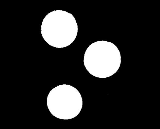
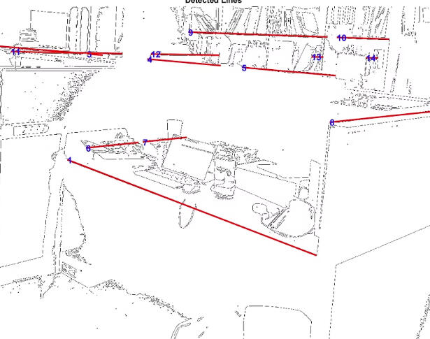
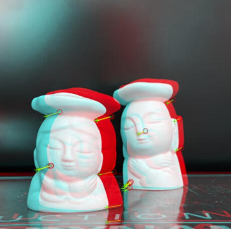
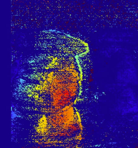
Image Processing (MATLAB)
Co-op 2 Personal Project
February 2024 - April 2024
Electrical Disconnect
Project Owner - Waterloo Rocketry
February 2023 - June 2023


pixel art robot
ME101 Term Project
January 2023 - April 2023
CAD & Simulation
Ongoing (Page Under construction!)

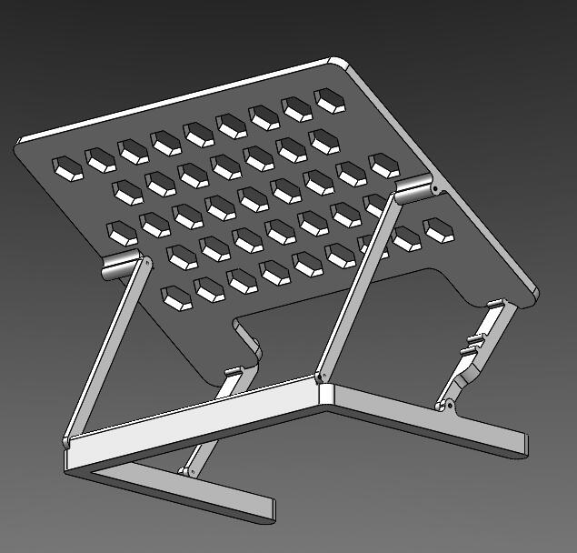
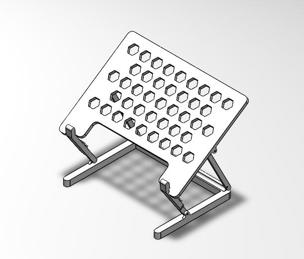
laptop stand
Designed to solve my Dell XPS from overheating
Image Processing (MATLAB)
Co-op 2 Personal Project
February 2024 - April 2024
Working at the KAIST Future Transport Power research lab, one of my main responsibilities was using MATLAB to collect data from high-speed camera engine experiment images. To complement the work I was doing for the lab, I embarked on a personal project throughout the term to use image processing techniques in various short-term projects primarily to detect edges of objects and measure distances in 2 and 3 dimensions. All images were taken with the iPhone 13 camera.

PROJECT 1: IMAGE SEGMENTATION
Using a photo of coins against a blank background for simplicity, this project focused on learning fundamental preprocessing techniques such as thresholding and opening, followed by image segmentation. I used this code to measure the area of a single coin in pixels.
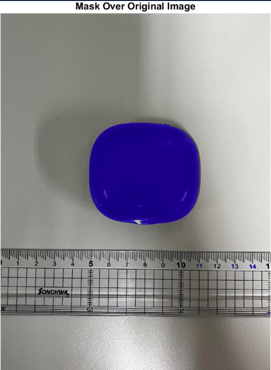
PROJECT 2: AREA OF AN OBJECT USING REAL-WORLD MEASUREMENTS
I continued with image segmentation but added a crucial step: converting the segmented mask's area to centimeters using a ruler in the picture as a reference scale. This involved determining the conversion factor from pixels to centimeters based on the ruler's dimensions. By integrating real-world measurements, I aimed to quantify the area of segmented objects accurately. This project provided practical experience in incorporating scale references for precise measurements in image processing applications.

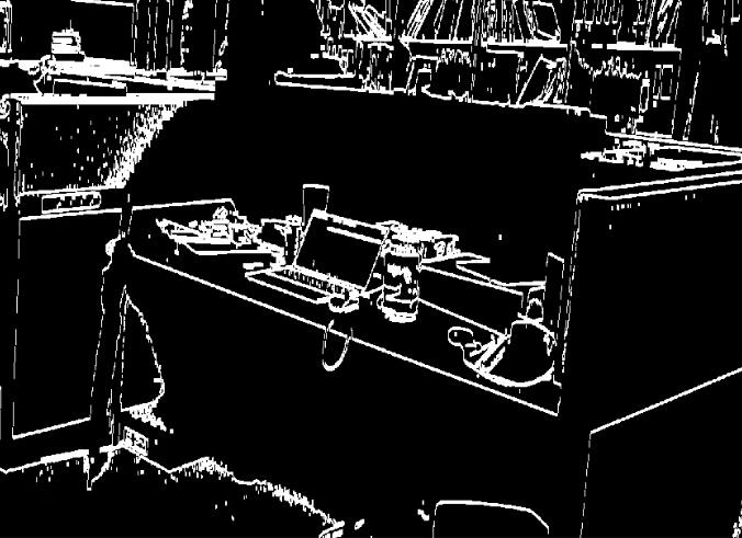
PROJECT 3: COMPARING EDGE DETECTION ALGORITHMS
Project 3 was a comparative study of three prominent edge detection algorithms—Canny, Sobel, and Fuzzy Logic—applied to the coin image.Canny Edge Detection: Renowned for its optimal performance in detecting edges with minimal noise, Canny edge detection involves multiple stages, including Gaussian smoothing, gradient calculation, non-maximum suppression, and edge tracking by hysteresis.Sobel Operator: The Sobel operator, a popular method for edge detection, employs convolution with two kernels to compute the gradient magnitude of the image. It's efficient and straightforward, making it a common choice for basic edge detection tasks.Fuzzy Logic-based Edge Detection: Unlike traditional methods, fuzzy logic-based edge detection incorporates fuzzy sets and membership functions to capture edge information in a more flexible and adaptive manner. This approach aims to address limitations encountered by conventional techniques, such as sensitivity to noise and varying image conditions.By comparing the performance of these algorithms on the coin image, I aimed to discern their strengths, weaknesses, and applicability under different scenarios. This project not only provided insights into the nuances of each edge detection method but also facilitated informed decision-making regarding algorithm selection for future image processing tasks

PROJECT 4: LINE DETECTION AND MEASURING DISTANCES
In the subsequent Project 4, I developed a line-detection algorithm with the capability to input a known distance within the image and output the length of a desired line in centimeters. The algorithm consists of the following stages:Input of Known Distance: The algorithm allows the user to input a known distance within the image, typically represented by a reference object with known dimensions, such as a ruler or a scale bar.Line Detection: Using the Hough transform, the algorithm identifies lines within the image. The user then inputs the line used as a reference and the line to measure.Scale Calibration: By referencing the known distance input by the user, the algorithm calibrates the image to establish a conversion factor from pixels to centimeters.Measurement of Desired Line: Once calibrated, the algorithm measures the length of the desired line in pixels and converts it to centimeters using the established conversion factor.By incorporating the ability to input a known distance, this project aimed to accurately measure different objects in the image using real-world units. For objects situated at a similar depth in the image, the measurement was accurate within 1 cm. However, I diagnosed some key limitations with this algorithm that impact its accuracy:1. The algorithm only detects straight lines and greatly favours horizontal orientations. Thus, the desired measurement must be a straight edge and vertical or diagonal edges in the image may not be detected. This could be addressed by adding another kernel to detect the vertical lines.2. The algorithm does not account for different depths within the image. Therefore, the accuracy variates depending on how close the depth plane of the desired edge is to that of the reference edge.Project 5 aimed primarily to address the latter issue.
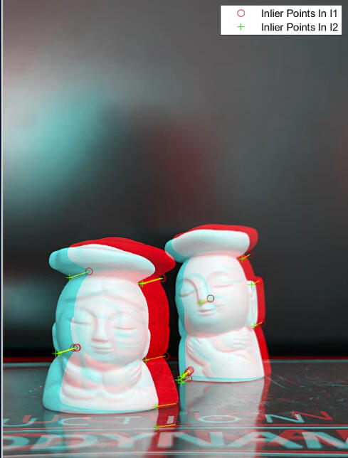
PROJECT 5: COMPUTER STEREO VISION
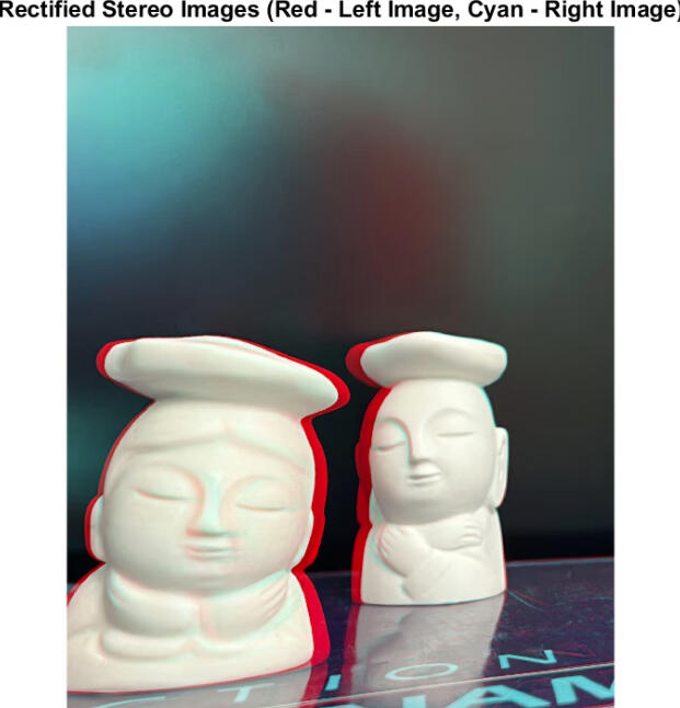
To address the issue of depth of field when measuring objects, I embarked on using computer stereo vision for depth estimation and scene reconstruction. Due to the unavailability of a dedicated stereo camera, I resorted to capturing two consecutive images using an iPhone to simulate stereo vision for this project. This made the task all-the-more challenging as I had to find a way to estimate the stereo parameters of the images, data that I would otherwise have with a typical stereo camera. This involved adding an extra step of checkerboard camera calibration.As seen in the images above, my first step was to rectify the stereo images, which is a process used in stereo vision to adjust two images so that corresponding points in both images lie on the same horizontal scanline. This alignment helps in matching corresponding features between the images, making it easier to determine disparities and compute depth information accurately. This was done by first detecting and matching SURF features (speeded up robust features). Then, the RANSAC algorithm was used to eliminate outlier points before performing the stereo rectification transformation.
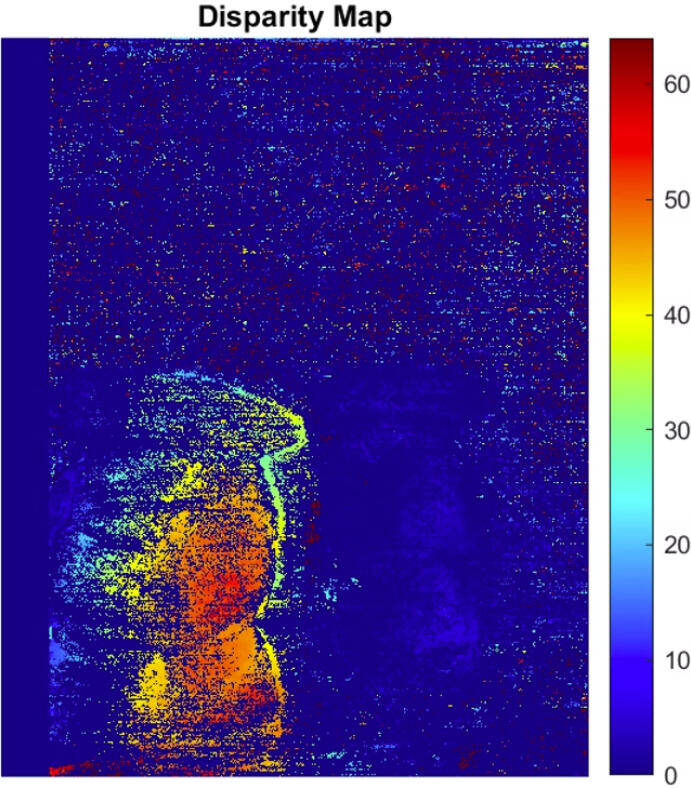
The disparity map seen on the right was computed from the rectified images using the Semi-Global Matching (SGM) algorithm. From here, the 3D scene can be reconstructed.
Skills developed
MATLAB Proficiency
Image Preprocessing
Edge Detection
Stereo Imaging
Critical Thinking & Problem Solving
Independent Work
Electrical Disconnect
Project Owner - Waterloo Rocketry
February 2023 - June 2023
Problem
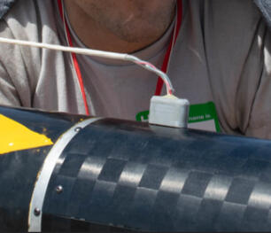
Previous rockets launched by the team did not feature an electrical umbilical. The assembly of the rocket was the last point that electronics could be fully charged, posing a severe issue for battery life of avionics.SOLUTION
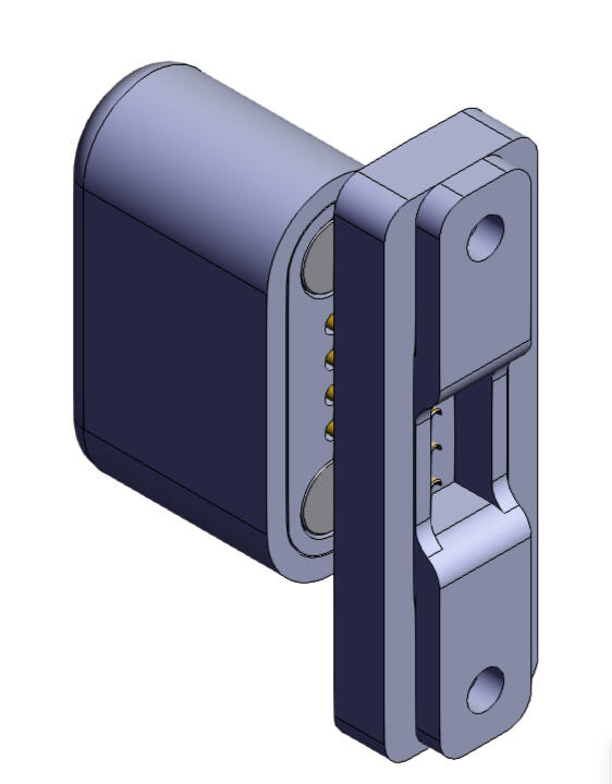
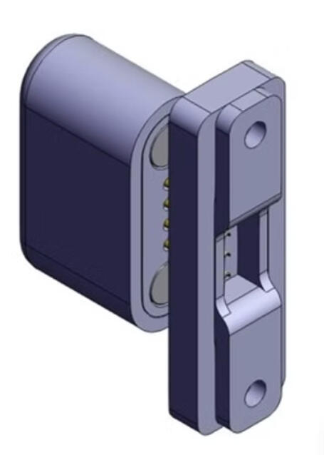
The electrical disconnect involved SLA-printed components with embedded magnets and electrical connectors to charge the rocket and was designed to shear from the rocket upon launch. The umbilical also allowed for wired comms as redundancy should wireless comms from mission control with the rocket fail prior to launch.Skills developed
Conceptual Design
Design Validation
Rapid Prototyping Process
Modelling CAD Assemblies
FDM & SLA Printing
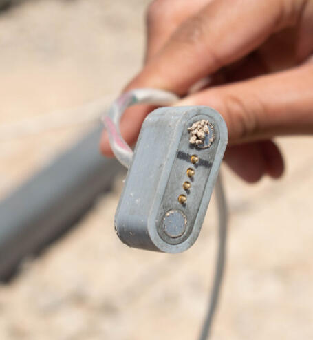
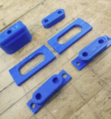
FINAL sla-pRINTED CONNECTOR
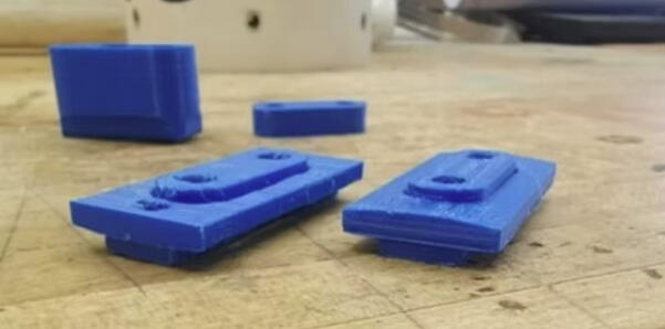
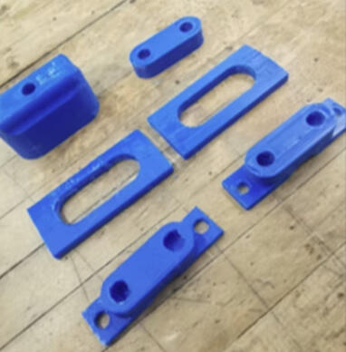
FDM Prototype
Design process
1. Evaluation of Problem & Needs Analysis
2. Review Existing Solutions (Other collegiate teams, industry)
3. Initial Design Sketch & Modification
4. CAD Model and Print of 1st FDM Prototype
5. Design Reiteration and Print of 2nd FDM Prototype (See left)
6. Design Validation
7. Final SLA Print and Integration Into Rocket Injector Section

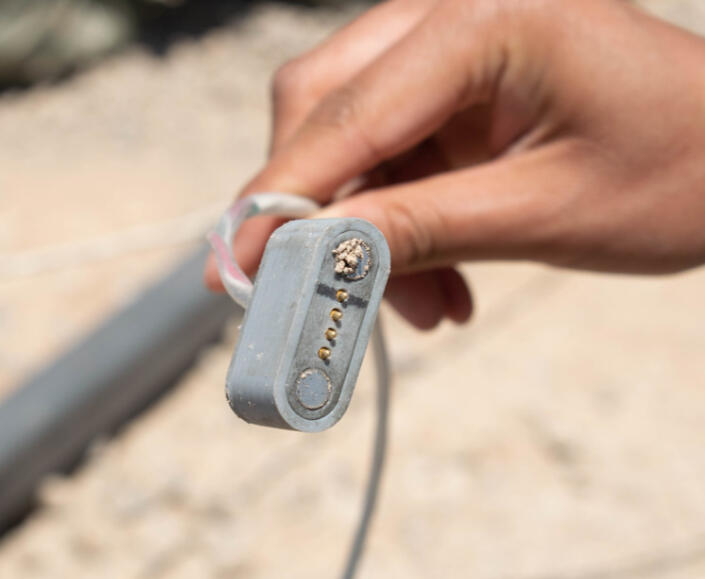
IN OPERATION ON THE LEVIATHAN OF THE SKY (2023) ROCKET
Disassembled prototype
pixel art robot
Project Owner - Waterloo Rocketry
February 2023 - June 2023
Full robot
PROBLEM
Assigned to design, construct, and program a robot to complete a desired task.
SOLUTION
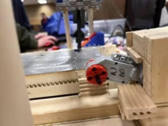
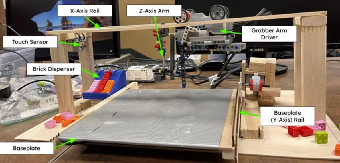
The Pixel Art Robot was designed to pick up Lego bricks from a dispenser and precisely place them onto a surface to produce pixel art. The 3-axis motion mechanism extrapolated from the mechanism of cartesian 3D printers
Stage 1: Grabber arm drives along top rail (x-axis) to brick dispenser. Arm is dropped down (z-axis) and picks up brick.Stage 2: Grabber arm drives along top rail to desired x-coordinate. Baseplate slides to desired y-coordinate.Stage 3: Arm is dropped down, releasing brick onto baseplate. Arm is raised and cycle begins again.Skills developed
Conceptual Design
Design Validation
Laser Cutting
C++ Programming
Critical Thinking & Problem Solving
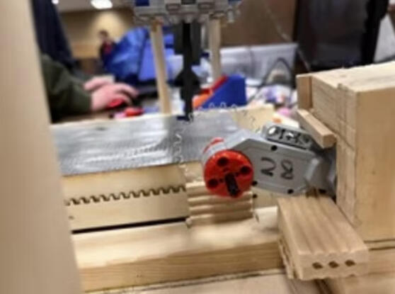
^ Baseplate Rack and Pinion
DESIGN PROCESS
Needs Analysis
Review Similar Devices (3D printers for motion control)
Conception of Mechanical Subsystems (ie. Arm, rails, baseplate, dispenser)
Construction of Subsystems
Programming of Software
Integration of Subsystems and Software
Design Validation
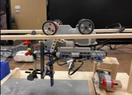
< Grabber arm mechanism
Personal
Cool stuff on the way! In the meantime, enjoy these photos from my travels: